Opening the Target Lift Settings Form
From within Orion:
1.From the Menu bar click on Athena -> Athena Unit Maintenance.
2.Select the target you wish to perform maintenance on. Only one may be selected.
3.From the form's menu click on Maintenance -> Target Lift Calibration.
Target Lift Setting Values
WARNING: Editing the Target Lift settings with incorrect values can damage your Target Lift and void your warranty.
Variable |
Meaning |
Default Value |
Initial Pulse |
Time, in microseconds of each pulse delivered to the stepper motor when the lift first starts moving. |
1500µs |
Final Pulse Down |
Time, in microseconds of each pulse delivered to the stepper motor, after the initial pulses, when moving the lift down. |
750µs |
Final Pulse Up |
Time, in microseconds of each pulse delivered to the stepper motor, after the initial pulses, when moving the lift up. |
950µs |
Switch Steps |
Number of steps to send the stepper motor at start up, using the Initial Pulse speed. |
1000 steps |
Seconds to Locate Sensor |
When the target lift is reset or is moving up, number of seconds to search for the lift sensor. |
180s |
Sensor value when found |
Electrical signal value of the target lift sensor, when the lift sensor is found. 1 indicates a HIGH voltage level, 0 indicates LOW. |
1 (HIGH). |
Variable "a" |
This is the first variable of the quadratic that now determines the amount of steps that need to be taken for a specific distance. |
0.00 This value is purposefully set lower than expected values, to prevent damage to the Target Lift. |
Variable "b" |
This is the second variable of the quadratic that now determines the amount of steps that need to be taken for a specific distance. This variable is the inverse of the steps / mm that was used previously. |
40.00 steps / mm This value is purposefully set lower than expected values, to prevent damage to the Target Lift. |
Variable "c" |
This is the third variable of the quadratic that now determines the amount of steps that need to be taken for a specific distance. This value represents the distance from the top of the target to the bottom of the top mount when the target is in it's standing state. |
5.00 mm This value is not mutable since is though be roughly the same on all units. |
Calculating Based on Two Measurements
The calculation of quadratic variables allow all lifts to be more accurate. This is done by measuring from two points, and calculating a best fit quadratic equation for the points input.
1.Click the "Run Test" button.
The Target Lift will first reset its position to the height of Standing. Then after a brief pause move to a short distance from Standing.
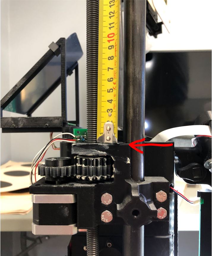
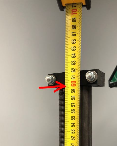
2.Once the Target Lift moves it's distance, measure the actual distance traveled. Measure, using millimeters from the top of the gear assembly to the bottom of the reference black.
|
|
Using millimeters, measure from the top of the gear assembly bracket. |
To the bottom of the reference block. |
3.Input the actual distance traveled into field one "Millimeters the first time" and hit Next.
4.The Target Lift will first reset its position to the height of Standing. Then after a brief pause move a slightly longer distance from Standing.
5.Once the Target Lift moves it's distance, measure the actual distance traveled. Measure, using millimeters from the top of the gear assembly to the bottom of the reference black.
6.Once finished, click Save, and test the targets calibration by selecting Target Height > Temporarily set Height > Kneeling.
Measuring using the style here, you should get between 605 mm and 595 mm.
Athena NC Target Lift Calibration Video Guide

